Fuel interception valves
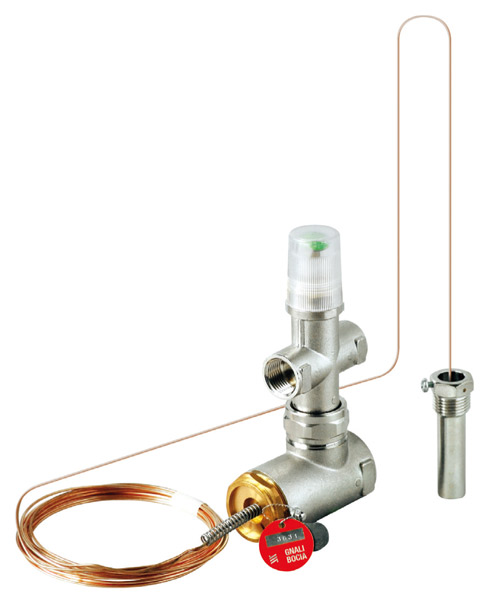 FUEL INTERCEPTION VALVE WITH POSITIVE ACTION, APPROVED AND CALIBRATED INAIL (Ex ISPESL)
The Fuel Interception Valve Gnali Bocia is a safety device to positive action, with manual reset, for which is provided to the calibration bench.
According to the provisions of the "Collection R" Ed. 2009 (application techniques Specifications of Title II of DM 01/12/75 pursuant to Art. 26 of the same decree), which apply to central heating systems employing hot water under pressure with temperature not exceeding 110° C, and overall maximum nominal power of the hearths (or maximum total thermal capacity of the hearths) exceeding 35kW, the advantages offered by using Fuel Interception Valves are considerably greater than those for Thermal Discharge Valves. In fact, when the request for Fuel Interception Valve is indicated, there is always an alternative possibility to use the Thermal Discharge Valve (self-activating valve, with positive safety, where the shutter opens due to the excessive high temperature and closes again when it decreases. This means that an amount of the produced heat is transferred to the outside, by the discharge of water, in order to reach the preset temperature limit the water itself). With the use of the Thermal Discharge Valve, depending on the type you expect, there are some disadvantages to consider, such as:
• if foreseen “with reinstatement”: in case of operation, the input of cold water causes drawbacks to the generator (thermal shock);
• if foreseen “without reinstatement”: in case of operation, the amount of discharged fluid can, in most cases, flood the boiler room.
Instead, with the use of the Fuel Interception Valve, the most obvious advantages are:
• easier installation: mounted on the fuel supply line upstream of the burner, if necessary intercepts and interrupts the supply (the Thermal Discharge Valve is in fact also connected to a Solenoid fuel Valve and/or a Valve that allows the reinstatement of the discharged fluid).
• the choice made by the plant designer is far simpler: its sizing is only made depending on the size of the fuel adduction pipes.
• much cheaper solution.
OPERATION
The Fuel Interception Valve Gnali Bocia is a safety device to positive action. Its purpose is to intercept and stop the fuel inflow to the burner, to avoid the achieving boiling temperature reached in the system’s supply circuit.
The Valve consist in two parts:
• The body of the valve through which the liquid or gas fuel flows.
• The control device fitted with a sensitive (diathermic fluid) element.
The valve shutter rod is connected to the control device so the valve can be closed (blocked) when:
a) the temperature of the heat transfer fluid (water) in output from the generator, exceeds the calibration value;
b)sensing element failure or rupture of the capillary tube (positive action), independently of temperature.
In the case of a block, the valve closes and can only be rearmed by manual intervention (this operation can occur when the temperature of the heat transfer fluid decreases below 87°C). The reset is not possible if the sensing element is faulty or the capillary is broken (positive action).
Under normal conditions (temperature less than 97°C) the rod (Ref. 5 - Fig. 1) rests on the control piston (Ref. 7 - Fig. 1) and the valve remains open.
If the piston moves to the left due to the expansion of the fluid content in the sensitive element (Ref. 9 - Fig. 1) it will cause the valve to close instantly.
If the piston moves to the right due to a leak of fluid from the capillary (breakage) it will cause the valve to close instantly.
To perform manual resetting (when the temperature decreases below 87°C) use the reset latch (Ref. 2 - Fig. 1).
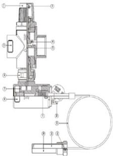
COMPONENTS
① Protective cap
② Reset knob
③ Safety Valve body
④ Shutter seal
⑤ Control rod
⑥ Connection ring nut
⑦ Control piston
⑧ Control device body
⑨ Bellows element
⑩ INAIL (Ex ISPESL) seal
⑪ Capillary tube
⑫ Bulb thermosensitive fixing screw
⑬ Thermosensitive bulb
⑭ Socket for thermosensitive bulb
CONSTRUCTIONAL FEATURES
Safety Valve body: Brass CW 617 N - EN12165
Control Device body: Brass CW 617 N - EN12165
Gaskets and O-Ring seal: NBR - EN 549
Capillary tube: Copper coated with black Polyethylene
Sensing element: Copper
Springs: Steel
Other components: Brass CW 614 N - EN12164 or Steel
OVERALL DIMENSIONS (mm)
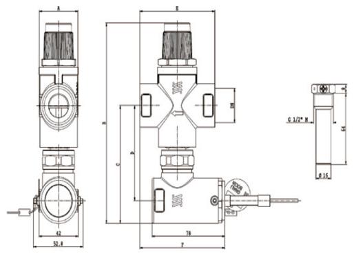
| CODE | DN | A | B | C | D | E | F |
| WP8030 | 1/2" | 27 | 164 +/-2 | 1.5 | 71 | 60 | 81 |
| WP8031 | 3/4" | 41.5 | 180 +/-2 | 106 | 85.5 | 80 | 91 |
| WP8032 | 1" | 41.5 | 180 +/-2 | 106 | 85.5 | 80 | 91 |
| WP8033 | 1" 1/4 | 48 | 180 +/-2 | 105.5 | 85 | 81 | 91.5 |
| WP8034 | 1" 1/2" | 74 | 205 +/-2 | 122 | 101.5 | 120 | 111 |
| WP8035 | 2" | 74 | 205 +/-2 | 122 | 101.5 | 120 | 111 |
TECHNICAL FEATURES
Nominal intervention temperature: 97°C
Calibration temperature: 97±3°C
Reset temperature: ≤ 87°C
Min/Max ambient temperature: 5/50°C
Max operating pressure: 6 bar
Max temperature thermosensitive bulb: 110°C
Max fuel temperature: 30°C
Capillary tube length: 5 m
Thermosensitive bulb sizes: Ø14 x 61 mm
Sensor pocket sizes: Ø16 x 72 mm
Sensor pocket connection: G 1/2" M
Connections valve body available: thread Female-Female G 1/2";
G 3/4"; G 1"; G 1"¼; G 1"½; G 2"
Types of fuel usable: Gasoil; burning Oil; Methane gas;
Gas of I, II and III family
THE CHOICE
The valve is produced in six different versions:
• Art. WP8030 DN 1/2" Kv = 1,8
• Art. WP8031 DN 3/4" Kv = 5,0
• Art. WP8032 DN 1" Kv = 5,3
• Art. WP8033 DN 1"¼ Kv = 16
• Art. WP8034 DN 1"½ Kv = 27
• Art. WP8035 DN 2" Kv = 31
To choose the right valve, it is not necessary to refer of to the generator power or to the static pressure, etc., it is enought choose the model with the same diameter equal to that of the fuel supply pipe. The DN 1/2" version is particularly suitable for gas-oil fuel; the loss of capacity provided by the valve during the flow gas-oil, with density 10,3 cSt, is:
• 100 Kg/h : 4 mm c. d’a.
• 150 Kg/h : 8 mm c. d’a.
• 200 Kg/h : 14 mm c. d’a.
Negligible losses in capacity, for the normal pipe lengths and burner suction pressures.
The valve to be used when the fuel is thick oil is generally the DN 3/4" or DN 1" version. The DN 1" version can be used with maximum capacities of 200 Kg/h of naphtha (density 100 cSt).
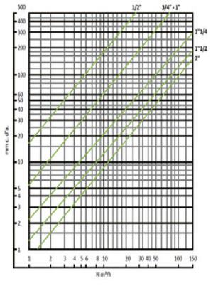
The DN 1"¼, DN 1"½ and DN 2" versions are normally used in gas systems. It is renowned that the most commonly used gaseous fuel is methane gas; this fuel is distributed at a relatively low pressure and therefore the interception valve has to provide a limited loss of capacity. To assist in this choice, we have indicated the features of the valves in Diagram 1. The diagram has been prepared, under an experimentation form, using methane gas; the drop in pressure in the valve can reach different values, according to the available pressure.
Generally methane is available at a pressure which varies from 600/700 and 150 mm c. d’a. from area to area and, very often, the pressure tends to decrease in the winter period when the request for fuel is at its highest. To avoid that the drop in pressure in the valve prevents the correct functioning of the burner, it is recommended to limit the loss of capacity in the valve. We consider that, in most cases, is not possible to foresee a drop in pressure over 40 mm c. d’a. for a valve; with this loss in capacity the level in N m³/h will be:
• DN 2" = 41 m³/h ≈ 350.000 Kcal/h.
• DN 1"¼ = 20 m³/h ≈ 170.000 Kcal/h.
• DN 1" = 7,5 m³/h ≈ 65.000 Kcal/h.
Evidently the verification of the pressure available upstream of the valve and the minimum level required by the burner will allow you, with the help of Diagram 1, to make a precise choice of the loss of capacity of the valve.
INSTALLATION
The installation (and any eventual maintenance operation) of the Fuel Interception Valve must be executed by Qualified Technical Personnel according to the instructions reported in this manual and in accordance with the current regulations.
It is recommended the respect of the following rules during installation phases:
• The valve must be installed on the fuel line, upstream of the burner, respecting the flow direction indicated by the relief arrow on the valve body (Fig. 4).
• In the connection phases of the valve to the pipes, pay close attention to not damage the capillary tube and/or the thermosensitive bulb.
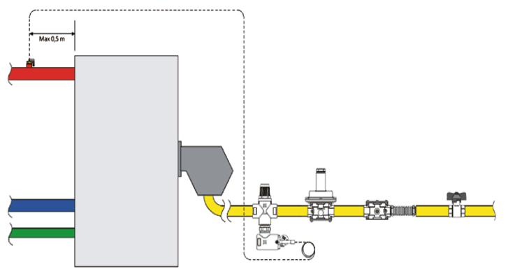
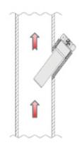
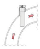
• The cockpit, for housing the thermosensitive bulb, must be completely immersed in the stream of the output fluid from the generator (Fig. 5, 6 and 7), within 0,5 m from the same generator (Fig. 4), upstream of any shut-off organ.
• Gently roll out the capillary tube and insert completely the thermosensitive bulb in the cockpit, and rewind the excess capillary tube in the proximity of the body valve. NB: during these steps must be taking all necessary precautions to ensure that the capillary tube doesn’t get crushed or bent excessively (R min = 50 mm).
• In order to avoid tampering or accidental spills of thermosensitive bulb (Ref. A - Fig. 3) from the cockpit (Rif. B - Fig. 3), secure the fastening of the same screwing completely the locking screw (Ref. C - Fig. 3) and plunging anything through pigtail and lead (Ref. D and E - Fig. 3) supplied with the Valve.
RESET PROCEDURE
During normal operation of the Fuel Interception Valve, the Green reset Knob is visible through the transparent part of the Protective Cap. In case of intervention (block), the reset Knob will drop in the knurled part of the Protective Cap and will no longer be visible through the transparent part.
NB: Before performing the reset procedure, make sure of the causes that caused the excessive temperature rise are followed by the blocking of the Fuel Interception Valve.
The reset operation can only be performed after the fluid temperature has fallen below 87°C (above this temperature the Valve can not be reset).
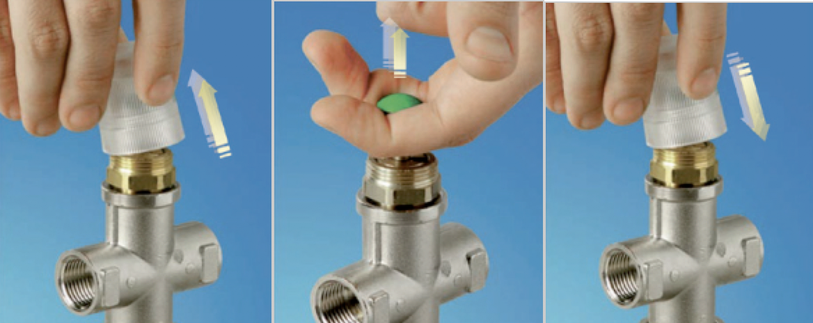
Manual reset is performed as follows:
• unscrew the protective cap (Fig. 8);
• pull the Knob up arrow (Fig. 9);
• replace the protective cover (Fig. 10).
In the event that the intervention (block) is due to the positive action (failure of the sensitive element or breakage of the capillary tube), the reset is not longer possible and the Valve must be replaced.
SAFETY
Installation, commissioning and any maintenance operation of the Fuel Interception Valve must be performed by qualified personnel, according to the instructions in this manual and in accordance with current regulations.
If the Fuel Interception Valve is not installed, commissioned and maintained properly, the safety instructions may not be warranted according to the instructions in this manual and in accordance with applicable regulations.
Always make sure that all connections are hydraulically sealed before commissioning.
During the installation phases, be careful to not overstretch the valve body threads over time (over time, cracks and possible leakage could occur).
In order to ensure the correct operation of the safety device, check and if necessary take appropriate precautions to prevent the capillary tube being crushed or bent excessively.
Water temperatures above 50°C can cause severe burns. During the installation, commissioning, and maintenance steps of the Fuel Interception Valve, take the necessary steps to ensure that such temperatures do not endanger people.
Leave this manual for use and service for any future consultation.
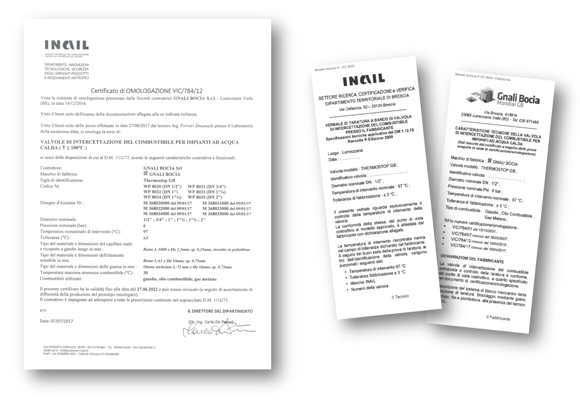
CERTIFICATION
The Gnali Bocia Fuel Interception Valve is a component that is defined as "INAIL approved (Ex ISPESL)". This type of device refers to the following document types:
1. APPROVAL CERTIFICATE:
This document certifies the approval of the Fuel Interception Valve Series, which is the object of the certificate itself. It is released by INAIL (Ex ISPESL) after successfully performing all tests and checks on Valve prototypes.
The Certificate of Approval has a validity of five years.
Each Valve of the series to which the Approval Certificate relates, produced during the validity period of the Certificate, is endorsed for an indefinite period.
2. VERBAL OF TABLE CALIBRATION:
It is the document certifying the testing and calibration of each single Valve. Testing and calibration of the Valve takes place in the presence of an INAIL Technician (Ex ISPESL) who draws, stamps and signs every single of each Valve after the successful completion of the test. This document also reports the Valve serial number, which corresponds to that reported on the sealed and plumbed aluminum plate, to the body of the control device of each Valve.
The Calibration Verbal is in a single copy and is supplied in original with the Valve, inside the packaging, it is therefore essential that it be stored with extreme care.
In case of loss of the original Calibration Verbal, a copy of the Cumulative Calibration Verbal may be required.
3. DECLARATION OF THE MANUFACTURER:
It is issued by the Manufacturer which declares the conformity of the item in question, from a constructive point of view, to the approved series/model, specified in the Approval Certificate.
